SubCO is part of the Soda Group | Learn more
UPDATES
The build progress of Australia’s newest transcontinental network
Follow the progress of SMAP as SUBCO builds one of the most powerful undersea cables in the world
Day 258
SMAP Build Progress
Commonwealth
New South Wales
South Australia
Victoria
Western Australia
Inshore
Deep Water
Terminal Equipment
Cables
Repeaters
System Assembly
Sydney
Melbourne (Torquay)
Adelaide
Perth
Cable Loading
Transit
Cable Laying
Sydney
Melbourne (Torquay)
Adelaide
Perth
Acceptance Testing
Provisional Acceptance
SLTE Integration
Project Meetup with ASN & OMS
April 30, 2024
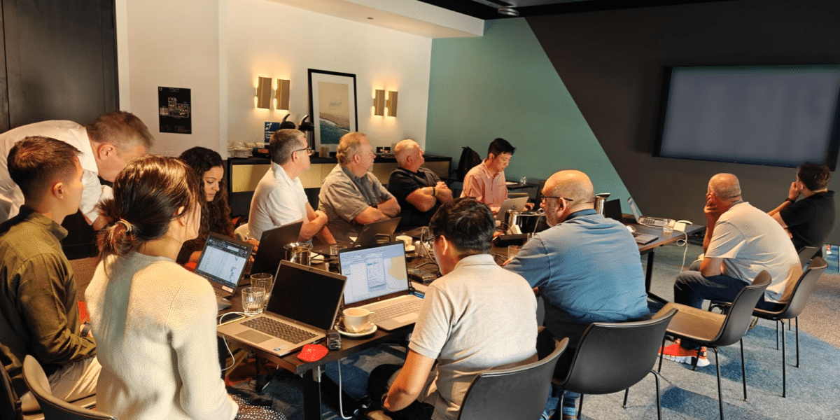
Last week, members of the SUBCO team met with key stakeholders from Alcatel Submarine Networks and Optic Marine Systems in Perth to discuss progression of survey work, scheduling matters and terrestrial & subsea infrastructure interface. Coordination meetings are regularly held with delivery partners, including our subsea suppliers, to ensure smooth progression of the project and works.
An in-person inspection was also held of key landing sites and infrastructure at Perth, where SMAP is scheduled to make its initial landing.
Monthly Meetup
April 23, 2024
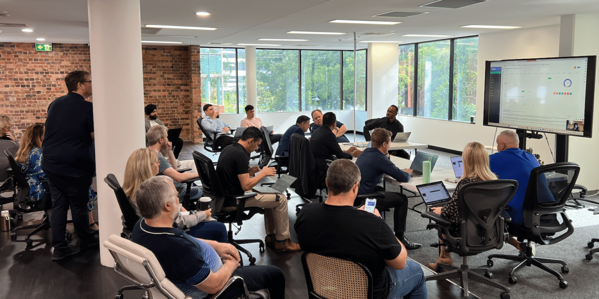
Each month, we coordinate a national on-site in Brisbane HQ with our SMAP Project Team. This meet up enables us to make all of our major decisions and discuss key project milestones. These meet ups have accelerated our program significantly given the nature of this complex build.
The Full Fibre Drop Branching Unit (FFU BU)
April 18, 2024
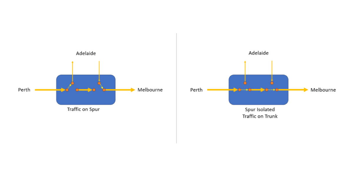
A key piece of technology used on SMAP is the Full FIbre Drop Branching Unit (FFD BU). The FFD BU allows SMAP to flexibly service drops to an intermediate location off one fibre pair whilst allowing the other fibres to run “express” through. This reduces the latency caused by dropping in and out of all intermediate destinations unnecessarily. It also maximises the capacity between end points as it ensures the minimum distance and therefore signal to noise (SNR) between end-points. A second advantage is that “”express”” traffic never needs to be routed over the spur cables so is, by definition, more secure (i.e. stays in deep water). The figure depicts a simple example of using an FFD BU to connect Adelaide.
SMAP Cable Structure & Design
April 15, 2024
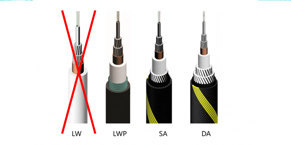
The submarine cable will be supplied and installed by Alcatel Submarine Networks. Also known as the wet segment, the submarine cable contains from 24 optical fibres which operate in pairs (12 pairs). The exact composition of the SMAP cable will vary along the route due to changing depths, laying methods and the risks associated with the section. However, there is one thing that is unique about the SMAP cable and we believe it’s a world first. For its entire route, the SMAP cable is 100% protected with metallic armouring!
SMAP is using either the Light-Weight Protected, Single Armoured and Double Armoured ASN variants. This additional investment in metallic armouring the entire cable is being made to maximise protection against shunt faults caused by cable abrasion on the ocean floor, thereby increasing the systems reliability and overall mean-time-between-failure (MTBF). SMAP is estimated to have a MTBF of greater than 10 years.
Examples of the types of cable are shown above. Before any protection is added to the cable the cable is 17mm in diameter. The first LWP cable is installed on benign seabeds while Double Armour (DA) is installed over more aggressive seabed conditions.
Sydney Fronthaul Underway
April 11, 2024
After many months of route surveys, planning and contractor negotiations the SUBCO team have signed the first major fronthaul contract which will establish new conduit and manholes suitable to land the new SMAP cable. The large dimensions of the cable to be hauled require the manufacture of some custom made duct for the project. In total the SMAP Sydney fronthaul will involve installation of 9kms of new duct and manholes.
What is Fronthaul?
Fronthaul is the section of network that houses the cable between the beach manhole (BMH) and the cable landing station (CLS) that houses the power feed equipment (PFE). The fronthaul will almost be entirely horizontally direction drilled (HDD) to reduce community impact and also provide greater network security as the HDD will on average be deeper underground than tradition excavation systems
Why are Manholes important?
Protection of Cables:
Cable manholes protect cables from environmental factors like moisture, temperature fluctuations, and physical damage. They provide a secure environment for the cables to ensure their longevity and performance.
Accessibility:
Manholes allow for easy access to cables for maintenance, repairs, and installations. Technicians can enter the manhole to work on the cables without the need to dig up the ground, making maintenance more efficient and cost-effective.
Routing and Distribution:
In complex cable networks, manholes serve as points for cable routing and distribution. They may contain junctions where cables from different directions or systems converge and are interconnected.
Safety:
Properly designed and maintained manholes enhance safety by preventing unauthorized access and reducing the risk of accidents related to exposed cables. They also facilitate emergency response by providing access points for troubleshooting and repairs.
Expansion and Upgrades:
Manholes accommodate future expansion and upgrades of cable infrastructure. As technology advances and network requirements evolve, additional cables or equipment can be easily installed within the manhole without major disruptions to the existing system.
Inshore Survey Drone Flyover in Sydney
April 4, 2024
We organised a drone fly over at south Maroubra Beach to capture some of the survey work taking place in preparation for the Sydney landing. This site will provide a greater resilience for our international network as no other cables currently land here. This location is also preferred because the installation process is less likely to cause disruption due to its open space.
To maximise survey thoroughness, the Team used a variety of methods including:
Multi-beam echo sounder – A type of sonar that is used to map the seabed. It emits acoustic waves in a fan shape beneath its transceiver. The time it takes for the sound waves to reflect off the seabed and return to the receiver is used to calculate the water depth.
Sub bottom profiler – A geophysical survey tool that uses sound to map beneath the seafloor. Low-frequency pulses of sound are aimed toward the seafloor, where some pulses penetrate through and are then reflected by subsurface sediment.
Grab sampling – A useful alternative for obtaining large volumes of surface sediments. Most types of dredge sampler are suitable for sampling in shallow water depths (< 20 m).
Land in Torquay officially acquired
April 2, 2024
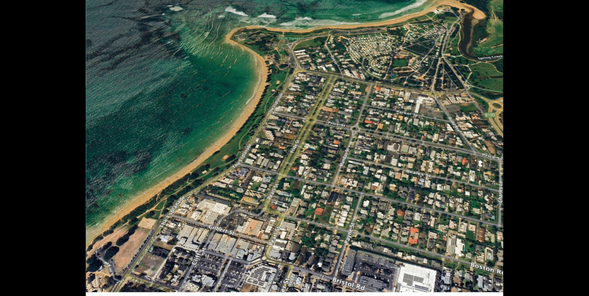
Torquay CLS land acquired! After months of due diligence, SUBCO is now unconditional on the purchase of land for our Torquay CLS. Architects and engineering consultants are completing final touches on our CLS design for approval and commencement of construction. The focus is on security and resiliency, yet also being low impact in every aspect. Exciting times indeed.
SMAP cable manufacturing has commenced!
March 26, 2024
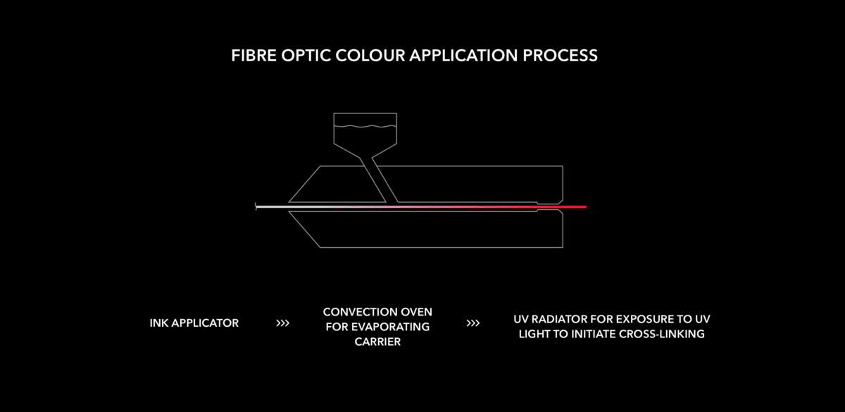
We’re pleased to announce that manufacturing has commenced, and the team at ASN are currently working on colouring the fibres individually. Fundamentally, this allows technicians to distinguish each cable – making it easier to splice and connect. To colour code optical fibres, an ultraviolet light-curable ink is mixed with a carrier fluid. This mixture is then applied to a horizontally moving optical fibre by an ink applicator. This process will be applied to over 150,000km of fibre
Torquay Cable Landing Station Land Contract Goes Unconditional
March 17, 2024
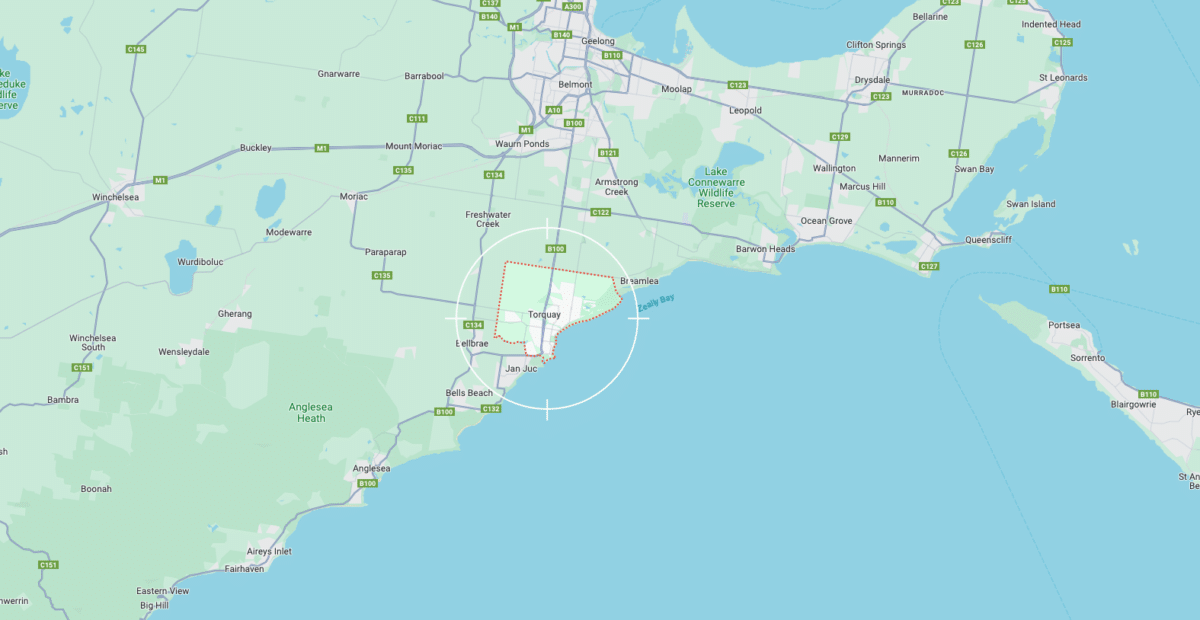
The Torquay Cable Landing Station (CLS) is one of two CLS projects that SUBCO is developing from the ground up as greenfield sites. SUBCO has signed a contract of sale for land which is now unconditional following due diligence, which included:
- A review of any planning controls which constrain how the site may be used and developed
- Detailed costing associated with site development
- Access to the location for the required fronthaul and backhaul conduit runs
- Access to services such as power supply.
The due diligence review highlighted a few approval steps to undertake for planning, but crucially highlighted little new Powercor infrastructure required to power the facility beyond a new ‘drop wire’ from the outside pole to a new pad-mount transformer on the property. The Team will now move to finalise the facility layout and external design before locking in contracts for the building construction.
In parallel, the Team has been finalising the design and route of the conduit requirements from the Beach to the new facility on the assumption that the site will proceed. The final fronthaul construction contracts will now be drawn up to begin the complex approval process in Victoria.
SMAP Project Secures approvals for Marine Survey
March 11, 2024
Final consents and permits have been put in place for the Marine Survey component of the project.
Over the past 6 months, SUBCO and its consultants have completed extensive Stakeholder consultations with Commonwealth and State based agencies in relation to the overall project and the specifics around the Marine Survey.
The process included:
- Project briefings, consultations, and RFIs with Commonwealth Agencies
- Briefings with State and Local Authorities and local recreational groups
- Consultation letters and briefing packs prepared and issued
- Engagement around specific permits and required approvals that have been secured – both Commonwealth, State and Local
- Notifications issued to affected stakeholders in regards to cable and other asset crossings to assist SUBCO with final cable placement and design